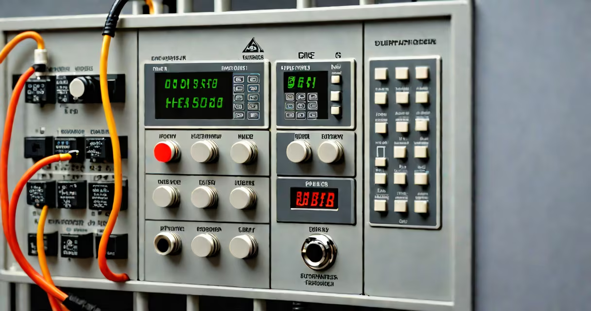
A PLC in electrical systems is a digital computer designed to monitor inputs, make decisions based on programmed logic, and control outputs in industrial environments. It replaces relay-based control systems with flexible, reprogrammable logic that adapts to changing production needs.
PLCs execute instructions stored in memory, responding to sensor signals and directing actuators such as motors, valves, and lights. They operate in harsh conditions-dust, vibration, temperature extremes-and are essential in automated machinery, assembly lines, and process control systems.
According to the International Electrotechnical Commission (IEC), PLCs must meet IEC 61131-3 standards for programming languages, safety, and reliability. These standards ensure consistent performance across manufacturers and industries.
The operation of a PLC follows a continuous cycle called the scan cycle. It reads input status from sensors and switches, executes the user program, then updates output devices like solenoids or motor starters.
Each scan takes milliseconds. For example, a typical industrial PLC completes a full cycle in 1-5 milliseconds. This speed enables real-time control in high-speed manufacturing, such as bottling lines or robotic welding cells.
During execution, the PLC evaluates logic conditions. If a sensor detects a metal part on a conveyor belt, the PLC triggers a pneumatic arm to push it into a bin. The decision is based on a program written in ladder logic-a visual programming format familiar to electricians.
A standard PLC consists of five core parts: power supply, processor (CPU), input modules, output modules, and communication interfaces.
The CPU handles program execution and internal processing. It runs firmware and manages data flow between memory, inputs, and outputs. Modern CPUs support multiple programming languages under IEC 61131-3, including structured text, function block diagrams, and instruction list.
Input modules accept signals from field devices. A 24V DC digital input module can read switch states from limit switches or photoelectric sensors. Analog input modules measure variables like pressure (4-20 mA signal) or temperature (thermocouple voltage).
Output modules drive actuators. Digital outputs switch relays or solid-state relays. Analog outputs control valve positions via 4-20 mA signals. A 16-channel digital output module can manage 16 machine tools simultaneously.
| Component | Function | Example Application |
|---|---|---|
| Power Supply | Converts AC to regulated DC for internal circuits | 24V DC supply powers a PLC in a factory control panel |
| CPU | Executes user program and manages system operations | Siemens S7-1200 CPU processes sensor data and controls a packaging machine |
| Input Module | Receives signals from sensors and switches | Photoelectric sensor sends 24V signal to a digital input channel |
| Output Module | Drives motors, valves, lights, and alarms | Relay output turns on a conveyor belt motor when a part is detected |
| Communication Interface | Enables network connectivity to HMIs, SCADA, or other controllers | Modbus TCP connection sends production data to a central monitoring system |
Many assume a PLC is just a fancy relay. While both respond to inputs and control outputs, a PLC offers far greater flexibility. A relay system requires rewiring for each change. A PLC only needs a software update.
Another misconception is that PLCs require advanced programming skills. Most industrial programs use ladder logic, which resembles electrical schematics. Electricians trained in relay logic can learn ladder logic in days, not months.
Some believe PLCs are obsolete due to cloud computing and edge AI. But PLCs remain critical at the operational level. They handle real-time tasks-like stopping a press when a safety door opens-faster than any networked system can. The National Institute of Standards and Technology (NIST) confirms that PLCs are still the primary choice for time-critical industrial control.
Consider a beverage bottling plant using a PLC to control a labeling machine. Four sensors detect bottle presence: optical, weight, position, and alignment. A 24V DC digital input module connects to each sensor.
The PLC runs a program that checks all four conditions. If a bottle passes inspection, the PLC activates a servo motor to apply a label. The output module drives a 24V relay that powers the label applicator.
If any sensor fails-say, the optical sensor detects no bottle-the PLC stops the line and triggers a red fault light. It logs the error code and waits for operator intervention. This entire sequence happens in less than 200 milliseconds.
When a new product line launches, engineers modify the PLC program to adjust label size and placement. No hardware changes are needed. The same PLC controls different products.
PLCs dominate industrial automation because they combine durability, precision, and adaptability. They operate reliably in temperatures from -25°C to +70°C and withstand electromagnetic interference common in factories.
They integrate with higher-level systems through protocols like Modbus, Profibus, and Ethernet/IP. A PLC can send data to a SCADA system showing real-time production rates, downtime events, and equipment health.
For example, a food processing facility uses a Rockwell Automation ControlLogix PLC to manage a pasteurization line. The PLC monitors temperature sensors, adjusts steam valves, and logs data for compliance with FDA regulations. If a temperature exceeds safe limits, the PLC shuts down the heater and alerts maintenance staff.
As noted in the IEEE Transactions on Industrial Electronics, PLCs are responsible for over 90% of discrete control tasks in manufacturing. Their role is not diminishing-it's expanding into hybrid systems that combine automation with predictive analytics.
Understanding the fundamentals of electrical systems, including the basics of circuit design and control theory, provides context for how PLCs interact with motors, sensors, and power distribution networks.
When troubleshooting a PLC-controlled system, start with the physical connections. A loose terminal on an input module can cause false triggers. Use a multimeter to verify voltage levels before assuming the program is faulty.
PLCs are not just machines-they're the nervous system of modern industry. From automotive plants to water treatment facilities, they ensure processes run safely, efficiently, and consistently. A single PLC in electrical systems can manage thousands of control points across multiple machines.