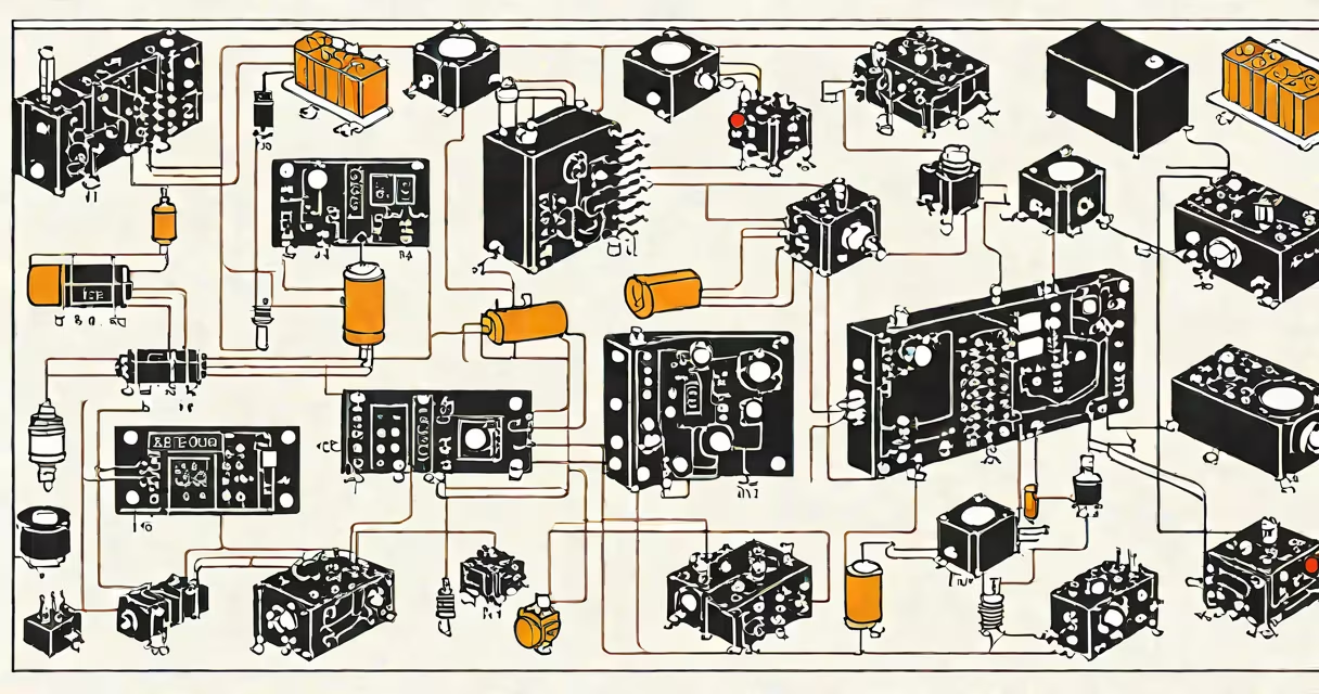
The fundamentals of electrical describe the core physical principles governing electric charge, current flow, voltage potential, and resistance in circuits. These principles form the basis for designing, analyzing, and troubleshooting all electrical systems-from household wiring to industrial control panels.
At its most basic level, electricity involves the movement of electrons through a conductor. This flow, known as current, is driven by voltage-the electrical potential difference between two points. Resistance opposes this flow and depends on material properties and geometry. Together, these three elements define how energy moves through a system.
Understanding these basics enables accurate prediction of circuit behavior. For example, a 12-volt battery connected to a 6-ohm resistor produces a current of 2 amps, calculated using Ohm's Law (I = V/R). This relationship underpins everything from lighting systems to motor controls.
Electricity operates through the interaction of four measurable quantities: voltage (V), current (I), resistance (R), and power (P). Voltage is measured in volts and represents the force pushing electrons. Current, measured in amperes, is the rate of electron flow past a point. Resistance, measured in ohms, limits that flow.
Ohm's Law (V = I × R) provides the mathematical foundation for analyzing simple circuits. If voltage increases while resistance stays constant, current rises proportionally. Conversely, increasing resistance reduces current. This principle allows engineers to size components correctly-for example, selecting a fuse that trips at 15 amps to protect a circuit rated for 120 volts.
Power, measured in watts, results from multiplying voltage and current (P = V × I). A 120-volt device drawing 2 amps consumes 240 watts. Power calculations are critical for energy efficiency and thermal management. Overloaded wires heat up due to resistive losses, which can cause fires if unchecked.
Every electrical system relies on specific parts that implement fundamental principles. Conductors like copper wire carry current with minimal resistance. Insulators such as PVC prevent unwanted current paths. Sources like batteries or generators provide voltage. Loads-resistors, motors, lights-consume energy.
Switches control current flow by opening or closing a circuit path. Fuses and circuit breakers protect against excessive current. A 15-amp breaker trips when current exceeds that limit, preventing overheating. These devices rely on the fundamentals: current generates heat proportional to I²R losses, and thermal sensors detect dangerous levels.
Modern systems integrate programmable logic controllers (PLCs) to automate processes. A PLC reads inputs from sensors, evaluates logic conditions, and sends outputs to actuators. For example, in a conveyor belt system, a photoelectric sensor detects a box, the PLC activates a motor via a relay, and the belt moves. This automation depends entirely on understanding voltage levels, signal timing, and current requirements.
Many assume electricity flows instantly through wires. In reality, electrons drift slowly-about 1 millimeter per second in typical copper wire-while the electromagnetic field propagates near light speed. The signal travels fast, but individual electrons move slowly.
Another error is thinking current is "used up" in a circuit. Current remains constant in a series loop; it doesn't disappear. Energy is consumed, not current. A 12-volt battery powers a 6-watt LED by delivering 0.5 amps continuously. The current entering the LED equals the current exiting-it's conserved.
Some believe higher voltage always means greater danger. While high voltage increases shock risk, low voltage can still be lethal under certain conditions. A 50-volt DC source can cause ventricular fibrillation if current passes through the heart. Safety standards require grounding and isolation even in low-voltage systems.
A residential lighting circuit illustrates multiple fundamentals. A 120-volt supply feeds a 60-watt incandescent bulb. Using P = V × I, the current is 0.5 amps. With a resistance of 240 ohms (R = V/I), the bulb converts electrical energy into light and heat.
Now consider a faulty connection. If the wire has 10 ohms of unintended resistance, power loss in the wire becomes I²R = (0.5)² × 10 = 2.5 watts. That heat can melt insulation over time. This demonstrates why proper wire gauge matters-thicker wires reduce resistance and minimize energy waste.
In industrial settings, three-phase power improves efficiency. A 480-volt three-phase system delivers more power with less current than single-phase equivalents. This reduces I²R losses and allows smaller conductors. Factories use this setup for large motors, where efficiency gains offset installation costs.
| Concept | Symbol | Unit | Role in Circuit |
|---|---|---|---|
| Voltage | V | volts (V) | Electrical pressure driving current |
| Current | I | amperes (A) | Rate of electron flow |
| Resistance | R | ohms (Ω) | Opposes current flow |
| Power | P | watts (W) | Energy consumed per second |
These values interact predictably. For instance, doubling voltage across a fixed resistance doubles current and quadruples power. This nonlinear effect explains why overvoltage events damage equipment-even small surges can destroy sensitive electronics.
I once encountered a malfunctioning control panel during a maintenance check. A motor wouldn't start despite correct voltage at the terminal block. Using a multimeter, I measured 120 volts across the input terminals but zero current. Tracing the circuit revealed a corroded connection in a junction box-resistance had risen to over 100 ohms. Replacing the connector restored normal operation.
This case showed that voltage presence doesn't guarantee functionality. High resistance at connections causes voltage drop and prevents sufficient current. It underscored the importance of testing both voltage and continuity. Even with correct voltage, poor connections fail under load.
Without mastery of the fundamentals, designing or repairing electrical systems leads to inefficiency, failure, or hazards. A technician who ignores resistance calculations may install undersized wires, leading to overheating. An engineer who misunderstands current flow might miswire a PLC input, causing false triggers.
Standards from the National Fire Protection Association (NFPA) and the International Electrotechnical Commission (IEC) enforce these principles. NFPA 70E outlines safe work practices, including arc flash boundaries based on fault current calculations. IEC 60364 covers low-voltage electrical installations, requiring adherence to voltage drop and short-circuit protection rules.
For anyone working with electrical systems, whether installing outlets or programming industrial controls, the fundamentals are non-negotiable. They ensure reliability, safety, and compliance. A deeper grasp of these principles enables faster diagnostics and better decision-making in complex environments.
When configuring a motor starter, for example, you must calculate inrush current and select a contactor rated above that value. Ignoring this step risks welding contacts shut. Understanding current and resistance prevents such failures.